
 EN

Hydrogen Microgrids for Off-Grid Resilience: System Architecture Basics
When a remote site cannot rely on a stable utility connection, a hydrogen microgrid integrated solution can turn variable renewable electricity into a managed energy service. The key is not simply adding an electrolyzer or a fuel cell. Resilience comes from assigning clear roles to generation, short-duration storage, hydrogen storage, power conversion, and supervisory control.
For B2B project teams, the first question is therefore not “Which component fits the application?” It is “What must the system keep running, for how long, and under what renewable conditions?” That boundary defines the architecture. More accurately, whether a design is suitable depends on load behavior, operating priorities, and the interfaces between subsystems.
Why off-grid resilience needs more than renewable generation
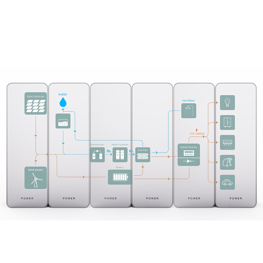
Solar and wind can reduce fuel dependence, but their output may not align with the load. A resilient hydrogen microgrid integrated solution manages that mismatch across time. During renewable surplus, an electrolyzer can use electricity to split water into hydrogen and oxygen. The stored hydrogen becomes an energy carrier that can be converted back to electricity later through a fuel-cell power block.
This is why off-grid hydrogen power is usually considered alongside batteries rather than as a direct replacement for them. Batteries are well suited to rapid balancing, start-up support, and short fluctuations. Hydrogen storage can be evaluated for longer gaps in renewable supply, where retaining usable energy over a longer operating window matters more than instant response alone. The right split must be verified against the site’s critical-load profile rather than assumed from a single component efficiency figure.
The five building blocks of a hydrogen microgrid system
1. Renewable generation and the electrical collection layer
The generation layer may combine solar PV, wind, or another available local source. Its purpose is to supply current loads first and create surplus energy when conditions allow. The collection layer includes the electrical pathways, protection, and conversion interfaces that bring generation into the microgrid bus. At this stage, teams should confirm expected seasonal production, curtailment risk, and whether the architecture will use AC, DC, or a hybrid bus.
2. Battery storage for fast balancing
A battery system commonly absorbs fast changes between generation and load. It can help stabilize voltage or frequency through the power-conversion system, bridge transitions between operating modes, and reduce unnecessary cycling of the hydrogen pathway. In a hydrogen microgrid integrated solution, the battery’s role should be defined by response speed and cycling needs, not by an expectation that it will cover every extended outage.
3. Electrolyzer and hydrogen production interface
The electrolyzer is the controllable load that converts selected surplus electricity into hydrogen. Its operating window must be coordinated with renewable availability, water supply, power quality, and the storage strategy. A practical design does not treat electrolysis as an isolated machine: it sets rules for when production starts, when it ramps down, and what reserves must remain for critical loads. This is especially important for off-grid hydrogen power, where exporting excess electricity may not be an option.
4. Hydrogen storage and conditioning
Storage provides the time-shift between production and power delivery. The design may include compression, pressure management, safety instrumentation, and a storage approach selected for the project’s site conditions. The architecture should also identify usable hydrogen inventory rather than only nominal capacity. Access, maintenance procedures, ambient conditions, and safety zoning are system-level questions that influence both layout and operational resilience.
5. Fuel-cell power delivery and load connection
When renewables and batteries cannot meet the demand, the fuel-cell power block converts stored hydrogen back into electricity. Its interface with inverters, switchgear, and load panels determines how reliably the microgrid can serve priority circuits. For an islanded site, confirm which device establishes the electrical reference, how black-start is handled, and how noncritical loads are shed. These details are often more consequential than comparing a single nameplate rating.
Control architecture: the layer that makes the system operate as one
An energy management system (EMS) coordinates the five building blocks. It receives data such as renewable output, battery state of charge, hydrogen inventory, load demand, and equipment availability. It then applies a dispatch hierarchy. A simplified hierarchy may prioritize renewable energy for active loads, use batteries for short transients, send qualifying surplus to electrolysis, and dispatch fuel-cell power when reserves or renewable conditions require it.
The control logic should include normal operation, low-renewable operation, planned maintenance, fault response, and restart. In other words, a hydrogen microgrid integrated solution needs both an energy-flow strategy and a protection strategy. Discussing system architecture without these operating modes can leave an otherwise credible design difficult to commission.
A practical architecture workflow for early project definition
- Classify loads. Separate critical, flexible, and deferrable loads. Record peak power, daily energy, start-up demand, and allowed interruption time.
- Characterize local energy. Review renewable resource patterns and identify the longest plausible low-generation periods that the system must address.
- Allocate storage roles. Define what batteries will handle quickly and what hydrogen storage must cover over longer intervals.
- Map interfaces. Specify the electrical bus, conversion stages, water and hydrogen boundaries, controls, protection, and communications.
- Test operating modes. Model normal dispatch, low-resource dispatch, maintenance, fault isolation, and restart before final equipment sizing.
This workflow moves the discussion from device parameters to system boundaries. It also helps project teams identify data that still needs validation, such as load growth, water treatment needs, autonomy targets, or fuel-cell ramp requirements.
Where an integrated solution fits
For teams evaluating a packaged starting point, Hyto Energy provides a Hydrogen microgrid integrated solution page that can be used to begin a technical conversation about system scope. The final configuration should remain conditional on the application boundary, load schedule, renewable profile, and required resilience period.
That conditional approach matters. A remote telecom site, island facility, industrial outpost, and community microgrid may all use off-grid hydrogen power, yet their architecture priorities can differ substantially. The most useful next step is to turn the resilience objective into a verified operating scenario, then size and control the system around that scenario.
Conclusion
A resilient hydrogen microgrid is an orchestrated system: renewable generation supplies energy, batteries manage fast changes, electrolysis captures selected surplus, hydrogen storage preserves energy across longer periods, fuel cells restore power, and the EMS coordinates every transition. Starting with loads and operating modes makes it easier to evaluate a hydrogen microgrid integrated solution without overpromising what any single component can achieve.